


 in the World of Online Casinos")


")
")


What is a PCB?
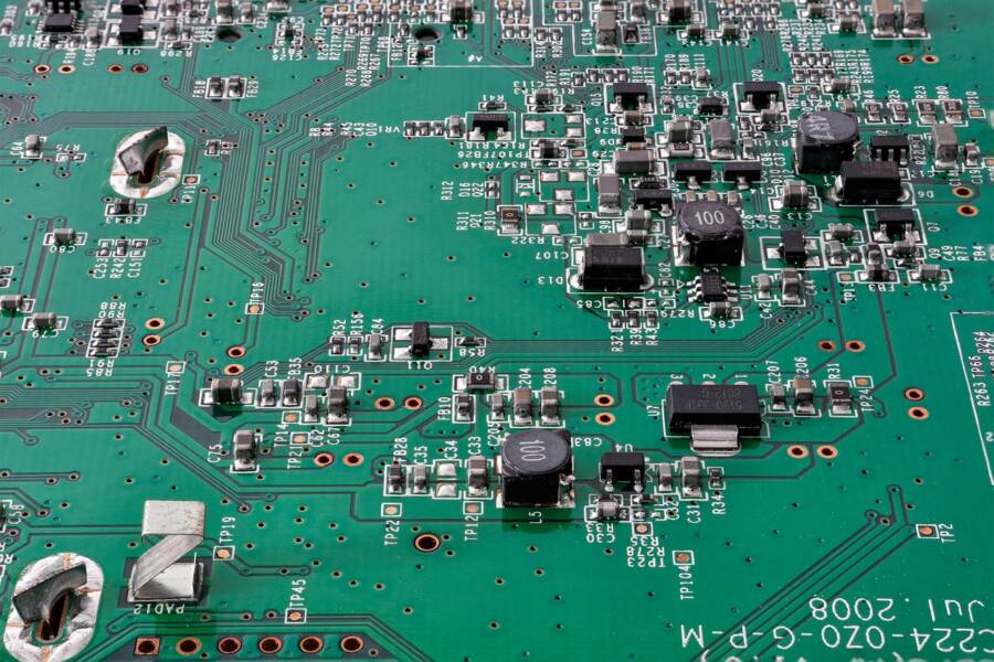
When you open an old or worn-out electronic device such as a remote or a simple toy, you will see a green element with silver threads and some components. That green sheet (sometimes red or blue) is known as PCB or Printed Circuit Board.
PCB is a board that has pads and lines connecting several points. It uses copper conductors to have electrical connections between elements. A PCB provides electrical connections and also affixes electronic components in designated locations.
Common applications of PCBs include computers, televisions, printers, stereos, musical instruments, appliances, mobile phones, and many other modern electronics.
Moreover, there are different types of PCBs. Common types include single-layer PCBs, double-layer PCBs, multilayer PCBs, rigid PCBs, Flex PCBs, metal PCBs, rigid-flex PCBs, and others.
Advantages of PCBs
*Saves time and space – one significant benefit of using printed circuit boards is that it saves space and time. It has managed to eliminate bulky components and wires and all the connections.
*Attached is a fixed place – no matter the board’s movements, PCB remains fixed in one place.
*Helps to eliminate loose connections – using PCBs is beneficial because it helps eliminate loose connections and short circuits. This is because it connects through copper tracks instead of connected elements.
*Reduces electronic noise – through the use of shorter pathways, PCBs have managed to reduce electronic noise. This leads to lower radiation and the pickup of electromagnetic waves.
*Cheaper to produce – compared to older models, PCBs are cheaper to the manufacturer. In addition, they are produced more rapidly. This is because they can be mass-produced.
Common used types of PCBs
There are different types of PCBs to consider. Some are classified based on mounting technology used, based on the number of layers, or they can be based on their flexibility.
1. Rigid PCBs
A rigid PCB is a solid, inflexible board that can be a single-sided PCB, double-sided PCB, or multilayer layer circuit board. It is a board that cannot bend or be forced out of shape. Hence, it is not flexible, and once it is manufactured, it cannot be folded or changed into another shape.
Benefits of rigid PCB
*It is cheaper compared to other PCB types like flexible PCBs
*It is durable
*Widely used in several electronic devices
*High quality and density
Uses of rigid PCB
*Computers and laptops
*Medical equipment
*Automotive’
*Aerospace
*Industrial equipment
2. Flex PCB
Even though the most used type of PCB is rigid, some electronic devices use flex PCBs. Flex PCBs are flexible circuit boards. It can be used on various electronic devices.
You can find single-sided flexible PCBs, double-sided flexible PCBs, and multilayer flex PCBs. One of the main benefits of flex PCB is that it can withstand high temperatures more than a rigid PCB.
Advantages of Flex PCBs
*Due to their flexibility, they can be used in a variety of products across industries
*Reduction in weight and size compared to other PCBs such as rigid circuit boards
*Can withstand harsh temperature conditions
*High circuit density
Applications of flex PCBs
Flexible PCBs are used in many sectors, including automotive, medical, smart, and aerospace.
3. Metal PCB
Metal PCB or metal core PCB is a printed circuit board with metal material as the base. Metal PCB is also known as metal-backed PCB or thermal PCB.
Most metal core PCBs are found in LED-lighting technologies such as motor control, motor drives, solid-state relays, solar panels, and power supply devices.
4. Multilayer PCB
A multilayer PCB is made up of three or more copper foil layers. It is one of the most used circuit boards because it is of high quality, has increased durability, and is more powerful than other printed circuit boards.
Compared to single-layer or double-layer PCBs, multilayer PCBs come with numerous benefits. For example, they are smaller in size than single-layer PCBs and lightweight. In addition, they have enhanced design functionality.
However, they are a bit expensive, limited availability, and have increased production time compared to single-layer PCBs.
Many industries prefer multilayer PCBs due to their several advantages. Some multilayer applications include consumer electronics, telecommunications, computer electronics, industrial, military gadgets, medical devices, aerospace, and automotive, among many others.
PCB manufacturing process
Even though printed circuit boards are small, their manufacturing process is very extensive. Whether you want to make one by yourself or want to engage a PCB manufacturer, there are several vital steps to observe.
The main steps of the PCB manufacturing process include:
1. The Design – A PCB design is needed before manufacturing a printed circuit board. The design is completed through computer software.
2. Printing the design – the next step is printing a design where a particular printer is used. The step is known as from the file to the film. The printer produces a film that shows layers and details of the board.
3. Printing inner layers – then, the design is printed to a laminate, and holes are drilled into the PCB to assist with the alignment.
4. Removing the unwanted copper – this is where any unwanted copper that remains on the board is removed.
5. Inspection – the layers are inspected for alignment. An optical punch machine drills holes and ensures the layers are lined up.
6. Drilling – holes are drilled on the board to expose the substrate and the inner panels.
7. Etching – a chemical solution is used to get rid of any excess copper.
8. Solder mask application – the other main step is solder mask application. The solder mask is applied on both sides.
9. Silkscreening – Here, the vital information is printed onto the board.
10. Surface finish – the PCB is plated with a solderable finish to boost the quality of the board.
11. Cutting – Using CNC milling machine to make a v-cut, that will help to separate the pcb from the board.
11. Testing – before a circuit board is considered complete, an electrical test is conducted on the board.
Conclusion
Printed Circuit boards are the backbone of modern electronics. However, it is essential to learn more about them before you request or start manufacturing. Keep in mind there are different types of PCBs, and the manufacturing process is very intense.
TechnologyHQ is a platform about business insights, tech, 4IR, digital transformation, AI, Blockchain, Cybersecurity, and social media for businesses.
We manage social media groups with more than 200,000 members with almost 100% engagement.


 in the World of Online Casinos")


